An article will help you understand what capacitor symbols are
Understanding Capacitor Symbols

I. Introduction
Capacitors are fundamental components in electronic circuits, playing a crucial role in various applications. They store and release electrical energy, making them essential for energy management, filtering, and timing functions. This article aims to demystify capacitor symbols, explaining their significance and helping readers understand how to interpret them in circuit diagrams.
II. Overview of Capacitors
A. What is a Capacitor?
A capacitor is a passive electronic component that stores electrical energy in an electric field. It consists of two conductive plates separated by an insulating material known as a dielectric. When a voltage is applied across the plates, an electric field is created, allowing the capacitor to store energy.
1. Basic Function and Operation
The basic function of a capacitor is to store and release energy. When connected to a power source, it charges up to the voltage of the source. When the power source is removed, the capacitor can discharge its stored energy back into the circuit, providing power to components that need it.
2. Types of Capacitors
There are several types of capacitors, each with unique characteristics and applications:
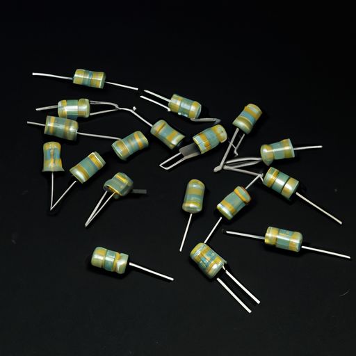
Ceramic Capacitors: These are non-polarized capacitors made from ceramic materials. They are commonly used in high-frequency applications due to their stability and low losses.
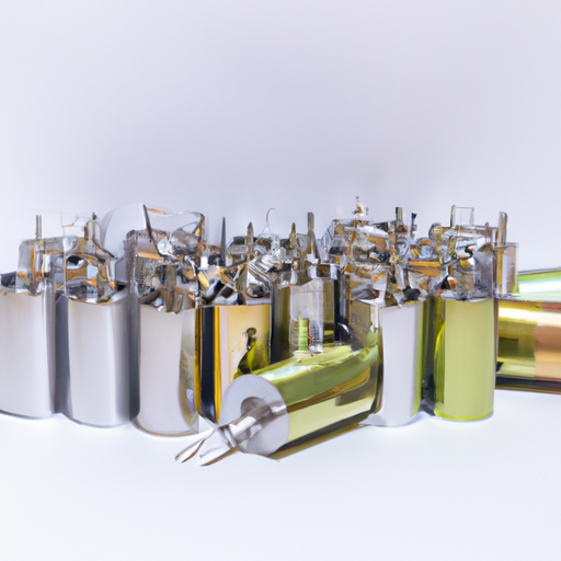
Electrolytic Capacitors: These are polarized capacitors that offer high capacitance values in a small package. They are often used in power supply circuits for smoothing and filtering.
Tantalum Capacitors: Similar to electrolytic capacitors, tantalum capacitors are also polarized but offer better performance in terms of stability and reliability.
B. Applications of Capacitors in Electronics
Capacitors are used in a variety of applications, including:
1. Energy Storage
Capacitors store energy for later use, making them essential in power supply circuits, where they smooth out voltage fluctuations.
2. Filtering and Smoothing
In power supply circuits, capacitors filter out noise and smooth the output voltage, ensuring a stable power supply for sensitive components.
3. Timing Applications
Capacitors are used in timing circuits, such as oscillators and timers, where they charge and discharge at specific rates to create time delays.
III. The Importance of Symbols in Electronics
A. Role of Symbols in Circuit Diagrams
In electronics, symbols are used to represent components in circuit diagrams. These symbols provide a visual shorthand that allows engineers and technicians to quickly understand the layout and function of a circuit.
B. Standardization of Symbols for Clarity and Communication
Standardized symbols ensure that everyone in the field can interpret circuit diagrams consistently. This is crucial for collaboration and communication among engineers, designers, and technicians.
C. Importance of Understanding Symbols for Engineers and Technicians
A solid understanding of symbols is essential for anyone working with electronic circuits. It enables professionals to read and interpret schematics accurately, troubleshoot issues, and design new circuits effectively.
IV. Common Capacitor Symbols
A. Basic Capacitor Symbol
The basic symbol for a capacitor consists of two parallel lines representing the conductive plates, with a gap between them indicating the dielectric.
1. Description and Components
The two lines are typically drawn vertically, with the left line representing the positive plate and the right line representing the negative plate in polarized capacitors.
2. Variations in Representation
In some diagrams, the capacitor symbol may include additional markings to indicate its type or characteristics, such as voltage rating or capacitance value.
B. Polarized vs. Non-Polarized Capacitors
1. Symbols for Polarized Capacitors
Polarized capacitors, such as electrolytic capacitors, are represented with a "+" sign next to the positive plate. This indicates the direction of current flow and the importance of connecting them correctly in a circuit.
2. Symbols for Non-Polarized Capacitors
Non-polarized capacitors, like ceramic capacitors, do not have a "+" sign and can be connected in either direction.
C. Specialized Capacitor Symbols
1. Variable Capacitors
Variable capacitors, which allow for adjustable capacitance, are often represented with a symbol that includes an arrow or a wavy line, indicating their adjustable nature.
2. Tuning Capacitors
Tuning capacitors, used in radio frequency applications, may have a similar symbol to variable capacitors but are often depicted with additional markings to indicate their specific function.
3. Supercapacitors
Supercapacitors, which have very high capacitance values, are represented with a symbol similar to standard capacitors but may include additional annotations to indicate their unique characteristics.
V. Understanding Capacitor Ratings and Values
A. Capacitance Value Representation
Capacitance is measured in Farads (F), with common subunits including microfarads (µF) and nanofarads (nF).
1. Units of Measurement
Farads (F): The standard unit of capacitance.
Microfarads (µF): One millionth of a Farad.
Nanofarads (nF): One billionth of a Farad.
2. How Values are Indicated in Circuit Diagrams
Capacitance values are often indicated next to the capacitor symbol in circuit diagrams, allowing for quick identification of the component's specifications.
B. Voltage Ratings and Their Symbols
Capacitors also have voltage ratings, which indicate the maximum voltage the capacitor can handle without failing. This is typically represented in circuit diagrams alongside the capacitance value.
C. Tolerance and Its Representation
Tolerance indicates the variation in capacitance value that can be expected. It is often represented as a percentage next to the capacitance value, providing insight into the reliability of the component.
VI. Reading Circuit Diagrams
A. How to Identify Capacitors in Circuit Diagrams
To identify capacitors in circuit diagrams, look for the capacitor symbols discussed earlier. Pay attention to any accompanying values or annotations that provide additional information about the component.
B. Examples of Circuit Diagrams with Capacitors
Consider a simple power supply circuit diagram. You may see several capacitors used for filtering, each with its symbol and values clearly indicated.
C. Importance of Context in Understanding Capacitor Symbols
Understanding the context in which a capacitor is used is crucial. For example, a capacitor in a timing circuit will have a different role than one used for filtering in a power supply.
VII. Practical Applications and Examples
A. Real-World Examples of Capacitors in Circuits
Capacitors are found in nearly every electronic device, from smartphones to computers. For instance, in a smartphone, capacitors help manage power supply stability and filter out noise in audio circuits.
B. Case Studies Highlighting the Role of Capacitor Symbols in Design
In designing a power amplifier, engineers must carefully select and place capacitors based on their symbols and ratings to ensure optimal performance and reliability.
C. Common Mistakes to Avoid When Interpreting Capacitor Symbols
One common mistake is misidentifying polarized capacitors, which can lead to incorrect connections and circuit failures. Always double-check the symbols and accompanying values before making connections.
VIII. Conclusion
Understanding capacitor symbols is essential for anyone working with electronic circuits. These symbols provide a visual language that simplifies the design and analysis of circuits. By familiarizing yourself with the various symbols and their meanings, you can enhance your ability to read and interpret circuit diagrams effectively.
As you continue your journey in electronics, take the time to explore other components and their symbols. Each element plays a vital role in the intricate world of electronic design, and a solid foundation in these concepts will serve you well in your future endeavors.
IX. References
For further learning, consider exploring the following resources:
Books: "The Art of Electronics" by Paul Horowitz and Winfield Hill
Websites: Electronics tutorials on sites like All About Circuits and Electronics-Tutorials
Online Courses: Platforms like Coursera and edX offer courses on electronics fundamentals and circuit design.
By delving deeper into these resources, you can expand your knowledge and skills in electronics, paving the way for a successful career in this dynamic field.