• هوائي PE51113-4: المواصفات التفصيلية، ومخطط الكسب والتردد

    The PE51113-4 antenna is a compact dual-band whip covering approximately 880–965 MHz and 1710–2170 MHz, with a nominal gain near 3 dBi and center points around 922.5 MHz and 1.94 GHz. This data-driven summary frames the article: full spec breakdown, plotting guidance for a gain chart across the frequency range, and practical installation and test steps tailored for US deployments. Background & product snapshot (background introduction) Quick technical snapshot (one-paragraph summary) Point: At-a-glance published specs summarize capability and installation fit. Evidence: Published spec fields typically list frequency ranges 880–965 MHz and 1710–2170 MHz, center frequencies 922.5 MHz and 1.94 GHz, nominal gain ~3 dBi, VSWR ≈2:1, 50 Ω impedance, vertical polarization, straight/whip form factor, two bands, common SMA/SMA-male or similar connector, and compact dimensions. Explanation: Use this compact table for quick procurement and site-fit checks. Field Published value Frequency ranges 880–965 MHz; 1710–2170 MHz Center frequencies 922.5 MHz; 1.94 GHz Nominal gain ~3 dBi VSWR target ≈2:1 (typical) Impedance 50 Ω Polarization Vertical Antenna type Whip / straight, 2-band Connector / mounting SMA-type or magnetic/base mount; verify variant Weight / dims Check published spec sheet for variant Why these specs matter for US networks Point: Frequency planning and physical pattern drive real-world performance. Evidence: The listed frequency range covers legacy sub-GHz IoT/LTE bands and the 1700–2100 MHz mobile/AWS bands used in many US installations. Explanation: A ~3 dBi vertical whip gives moderate omnidirectional horizontal coverage and tight elevation pattern—suitable for gateways, backhaul segments, and small-cell feeders where vertical polarization and modest gain balance coverage versus size and wind load. Technical specifications — fields explained (data analysis) Electrical specs: impedance, VSWR, and efficiency Point: Electrical metrics determine how much transmitted power becomes radiated signal. Evidence: Typical published impedance is 50 Ω and VSWR is listed ≈2:1 across each band; for a 2:1 VSWR the return loss is about 6.0 dB (RL = -20·log10((VSWR-1)/(VSWR+1))). Explanation: For a 2:1 VSWR, expected mismatch loss is roughly 0.5 dB, so system designers should budget that loss into link budgets. The PE51113-4 antenna can be treated as a ~3 dBi device, but measured efficiency and spectral variation should be checked during commissioning. Whip Element (~3 dBi) GND PLANE SMA CONN RF IN (50 Ω) 880-965 MHz 1710-2170 MHz Mechanical & environmental specs: mounting, wind load, connectors Point: Mechanical fit and outdoor rating affect longevity and performance. Evidence: Common whip variants ship with magnetic or fixed-base mounts and SMA-type connectors; cable loss increases with length (e.g., RG-316 vs LMR-400 differences). Explanation: Specify low-loss coax for runs >3–5 m, confirm connector gender and torque specs, and verify IP/wind ratings in the published datasheet before outdoor exposure. Label units and mounting clearances in purchase orders to avoid on-site surprises. Gain & frequency chart — data, plotting & interpretation (data + charts) Gain vs frequency: recommended chart & annotations Point: A gain chart visualizes frequency-dependent behavior that the nominal 3 dBi hides. Evidence: Plot measured or supplier gain across 880–2170 MHz with X axis in MHz and Y axis in dBi, showing at least 8–12 points per band and a smoothed curve; annotate center points near 922.5 MHz and 1.94 GHz, mark band edges and any peaks/troughs. Explanation: The gain chart clarifies where gain rises or dips relative to the nominal value and guides tuning; include alt text like “Gain chart: PE51113-4 antenna, gain vs frequency (880–2170 MHz)”. VSWR & impedance plots (companion chart) Point: VSWR plots reveal usable bandwidth and mismatch hotspots. Evidence: Plot VSWR across the same frequency range and use Smith chart insets for critical bands; identify frequencies where VSWR exceeds the ≈2:1 target. Explanation: When VSWR spikes occur, corrective options include a matching network, changing feed cable, or slight mechanical repositioning. Use these plots to set pass/fail criteria for field acceptance. Installation, tuning & testing guide (method/guideline) Pre-install checklist & cable selection Point: Proper planning minimizes unexpected loss and rework. Evidence: Measure cable runs; calculate feedline loss at center frequencies (feedline insertion loss increases with frequency); select LMR-200/240/400 equivalents depending on run length. Explanation: For runs under 3 m, an economical low-loss coax is acceptable; for longer runs use higher-spec cable. Verify connector type, torque values, grounding, and lightning protection before final mounting. On-site tuning & verification (field test procedure) Point: Field tests validate published specs and installation quality. Evidence: Sweep the antenna with a VNA to capture S11/VSWR, record gain/profile if available, and log RSSI/SINR from a known transmitter at multiple azimuth/elevation angles. Explanation: Pass criteria examples: VSWR ≤2:1 across target band or mismatch loss
  • PE51113-2 هوائي مغناطيسي ثنائي النطاق: المواصفات الكاملة

    The dual-band magnetic mount antenna delivers measured coverage across 880–965 MHz and 1710–2170 MHz with a nominal 3 dBi peak and a 50 W power handling class. This component is engineered for mid-power mobile and temporary deployments where rapid installation and reliable RF performance are critical. Electrical Parameter Specification Value Frequency Range 1 880 – 965 MHz Frequency Range 2 1710 – 2170 MHz Nominal Peak Gain 3 dBi VSWR (Typical) < 2.0:1 Input Impedance 50 Ω Max Input Power 50 Watts 1 — Product Overview & Design Intent The PE51113-2 is designed specifically for vehicle-top and temporary field deployments. Its magnetic base allows for non-destructive mounting on any ferrous surface, serving as an ideal solution for repeater feeds, mobile voice/data enhancement, and temporary site coverage. Radiating Whip Magnetic Base (GND) RF Coax Out 2 — Electrical & Mechanical Deep-Dive 2.1 RF Performance Metrics The antenna utilizes vertical polarization to align with standard cellular base station signals. While the azimuth pattern is omnidirectional, users should note that mounting near vehicle edges or large metallic obstructions can skew the radiation lobes, potentially creating nulls in specific directions. 2.2 Physical Integration The mechanical interface typically features a standard RF connector (such as N-Female or SMA, depending on configuration). The magnetic base provides sufficient holding force for standard highway speeds, though surface preparation is required to prevent paint abrasion and ensure a proper capacitive ground plane coupling. 3 — Installation & Testing Guide To maximize the link budget, follow these industrial best practices: Placement: Center the magnet on the roof for optimal ground-plane symmetry. Cable Choice: Replace standard RG-58 with low-loss LMR-200 or LMR-400 for runs exceeding 3 meters to mitigate signal attenuation at 2.1 GHz. Verification: Perform a VSWR sweep post-installation. A reading above 2.0:1 usually indicates a poor ground plane or damaged cable assembly. 4 — Comparison & Maintenance When comparing the PE51113-2 to "rubber duck" or glass-mount alternatives, the magnetic mount consistently offers superior gain due to the utilization of the vehicle's metal body as a reflective ground plane. Periodic maintenance should include checking the magnet's protective coating for corrosion and ensuring the connector remains hand-tight and moisture-free. Summary Dual-Band Versatility: Supports legacy 900MHz and modern 2.1GHz data bands. Field Ready: 50W power handling and magnetic mounting for rapid deployment. Performance Tip: Use low-loss cabling and center-mount placement to realize the full 3 dBi gain potential. Frequently Asked Questions How do the PE51113-2 specs affect vehicle signal improvement? Real-world improvement depends on replacement baseline and system losses. A ~3 dBi antenna improves margin modestly compared with stock short antennas. Gains of a few dB are typical if cable/adapters are low-loss. To maximize improvement, use center roof placement and low-loss coax; measure RSSI before and after installation to quantify benefit. What VSWR and power limits should I expect for this dual-band magnetic mount antenna? Expect VSWR under 2:1 across each band and a power handling near 50 W as standard benchmarks. Datasheet-level numbers are nominal; measured plots may show variation by mount and vehicle ground plane. Always perform an on-vehicle SWR sweep post-install to confirm acceptable return loss for your transmitter power. Which cable and connector choices minimize loss for mobile installs? Use impedance-matched, low-loss cable (LMR series) and minimize adapters. RG-58 introduces higher loss at higher frequencies; LMR-200/400 reduces that loss significantly. At 2 GHz, RG-58 can cost several dB over a few meters versus lower-loss options. Choose proper cable length and factor cable loss into link-budget calculations. Where is the optimal placement for a magnetic mount antenna? Center the magnet on a large, flat metal surface (like a vehicle roof) where possible. This provides the best ground-plane symmetry, ensuring the radiation pattern remains omnidirectional and the VSWR stays within the specified range. Avoid placement near edges or other vertical antennas to prevent pattern distortion. Final takeaway: verify connector and cable compatibility, run an SWR test after installation, and use the procurement checklist before buying the PE51113-2.
  • مستشعر الأكسجين AA428-210 AO2: المواصفات الكاملة والبيانات

    يعد AA428-210 مستشعر أكسجين كهروكيميائي عالي الدقة مصمم للمراقبة الصناعية للأكسجين وتحليل غازات العادم. تم تصميمه كخلية غلفانية، حيث يقوم بتحويل الضغط الجزئي للأكسجين إلى إشارة ملي فولت تناسبية. مع مخرج اسمي يتراوح بين 9–13 ملي فولت في الهواء المحيط ونطاق تشغيل قوي من -20 درجة مئوية إلى +50 درجة مئوية، فإنه يعمل كمكون حيوي في أنظمة التحكم في الاحتراق والسلامة البيئية. المعلمة (Parameter) القيمة النموذجية حدود التشغيل جهد المخرج (الهواء) 9 – 13 ملي فولت دائرة مفتوحة عند 20.9% O2 وقت الاستجابة (T90) < 40 ثانية تدفق جوي قياسي نطاق درجة الحرارة -20 إلى +50 درجة مئوية يتطلب تعويضاً حرارياً قياسياً نطاق الضغط 0.5 – 2.0 بار نسبةً إلى الضغط المحيط نوع الموصل Molex بـ 3 دبابيس مخطط VCC, GND, OUT خلية كهروكيميائية دبوس 1: Vref دبوس 2: OUT دبوس 3: GND مدخل O2 نظرة عامة ومبدأ العمل يعمل AA428-210 بناءً على مبدأ الضغط الجزئي الكهروكيميائي. ينتشر الأكسجين عبر غشاء للوصول إلى قطب الاستشعار، مما يؤدي إلى تفاعل أكسدة واختزال. تولد هذه العملية تياراً منخفض المقاومة، يتم تحويله داخلياً إلى مخرج ملي فولت. يسهل هيكله الأسطواني المصنوع من مادة ABS وكتلته التي تبلغ حوالي 40 جراماً دمجه في الأجهزة التي تُثبت على اللوحات أو الأجهزة المحمولة. التكامل وتكييف الإشارة نظراً لانخفاض المخرج (9–13 ملي فولت)، يجب على مصممي الأجهزة تنفيذ تضخيم عالي الكسب ومنخفض الضوضاء. بالنسبة لمحول ADC الخاص بمتحكم دقيق يعمل بجهد 3.3 فولت، يوصى بكسب حلقة مغلقة يبلغ حوالي 230 ضعفاً. تعد مضخمات العمليات الدقيقة من نوع Rail-to-Rail ذات جهد الإزاحة المنخفض (على سبيل المثال، أقل من 50 ميكرو فولت) مثالية للحفاظ على الخطية وتقليل الانحراف الحراري. يعد استخدام الكابلات المحمية إلزامياً للمسافات التي تتجاوز 0.5 متر لمنع تداخل التداخل الكهرومغناطيسي (EMI) مع إشارة الملي فولت الحساسة. الاختبار والصيانة يجب أن تتبع المعايرة روتيناً من نقطتين "الصفر/المدى". استخدم النيتروجين (0% O2) لنقطة الصفر والهواء المحيط (20.9% O2) أو مزيج غاز معتمد لنقطة المدى. عادةً ما يُستدل على نهاية العمر الافتراضي من خلال انخفاض كبير في جهد مخرج الهواء المحيط أو زيادة في وقت الاستجابة تتجاوز 60 ثانية. الأسئلة الشائعة ما هو المخرج المتوقع بدون حمل وكيف يجب استخدامه في التصميم؟ المخرج بدون حمل في الهواء المحيط هو 9–13 ملي فولت. استخدم هذه القيمة لحساب كسب المضخم (مثلاً: الكسب = أقصى جهد ADC / أقصى جهد للمستشعر). قم دائماً بتضمين هامش أمان بنسبة 10% لمراعاة انحراف المستشعر وتأثيرات درجة الحرارة. ما هي دقة ADC الموصى بها لهذا المستشعر؟ يعد ADC بدقة 12 بت هو الحد الأدنى للتطبيقات الصناعية، حيث يوفر دقة تبلغ حوالي 0.8 ملي فولت بعد تضخيم قدره 230 ضعفاً. للمراقبة عالية الدقة، يفضل استخدام ADC بدقة 16 بت مع تقنية زيادة العينات (oversampling) لتصفية ضوضاء التكميم. ما هو وقت الاستجابة النموذجي (T90)؟ وقت الاستجابة T90 عادة ما يكون أقل من 40 ثانية. وبينما هو مناسب لمعظم المراقبة الصناعية، فقد يتطلب تعويضاً رقمياً إذا تم استخدامه في التحكم في الاحتراق ذو الحلقة المغلقة عالي السرعة. كم مرة يجب إعادة معايرة المستشعرات أو استبدالها؟ يجب إجراء إعادة المعايرة كل 3 إلى 6 أشهر اعتماداً على قسوة البيئة. الاستبدال مطلوب عندما لا يعد بالإمكان معايرة المستشعر لغاز المدى أو عند حدوث استنزاف فيزيائي للقطب (يظهر من خلال الاستجابة البطيئة). قائمة التحقق النهائية نطاق المخرج: تأكد من مخرج 9–13 ملي فولت في الهواء المحيط قبل إجراء القياس. الدوائر: استخدم مضخمات عمليات منخفضة الضوضاء بكسب يبلغ حوالي 230 ضعفاً لأنظمة 3.3 فولت. الحماية: قم بتضمين فلاتر تمرير منخفض RC (2-5 هرتز) وصمامات ثنائية TVS للحماية من التيارات العابرة. الصيانة: حدد مواعيد دورية لفحص المدى وتتبع عمر المستشعر للاستبدال الاستباقي.
  • BCM5488A7IPBG وثيقة البيانات ملخص: المواصفات والمقاييس الرئيسية

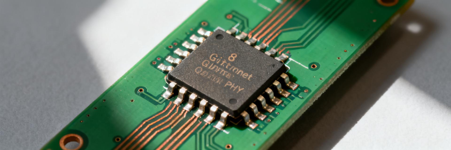
    Measured in typical deployments, the BCM5488A7IPBG supports line-rate Gigabit performance across eight PHY channels with power profiles commonly reported near 3.5–6.0 W per device under mixed traffic load. This figure sets the baseline for PCB thermal planning and supply budgeting in multi-port Gigabit designs. Device Overview & Primary Use Cases The part is optimized for high-density multi-port Gigabit PHY roles in switches, routers, and embedded network appliances. Proper identification and mechanical constraints are critical for first-spin success. AttributeTypical Value Package TypeQFN-like, Exposed Thermal Pad Pin Count~64-100 Pins (Consult Mechanical Drawing) Port Count8-Port (Octal) 10/100/1000BASE-T Typical FootprintThermal via array center; 0.8mm+ pitch BCM5488A7 8x RJ45 MAC (SGMII) Thermal Pad (GND) VCC / AVDD Core Electrical & Performance Specifications Interface support determines host-side connectivity. Common interfaces include RGMII and SGMII, requiring precise clocking and management via the MDIO bus. InterfaceSignals & Timing RGMIITX/RX data nibbles, TX/RX clocks, control SGMIISerialized MAC link, differential clocking MDIO/SMIManagement bus for register access (IEEE 802.3) Integration & Design Guidance Layout choices directly impact performance. Implement thermal via arrays (staggered) under the thermal pad and place 0.1–10 µF decouplers within millimeters of supply pins. Verify power rails and voltages at test points before applying reset. Confirm MDIO access by reading the PHY Identification Registers. Validate link stability and BER (