PTVS6V0P1UP TVS Diode: Latest 600W Specs & Test Data

PTVS6V0P1UP TVS Diode: Latest 600W Specs & Test Data
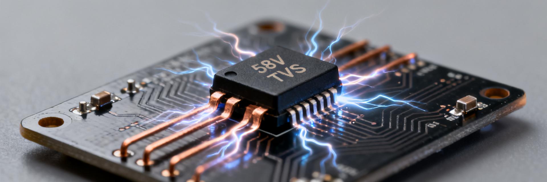
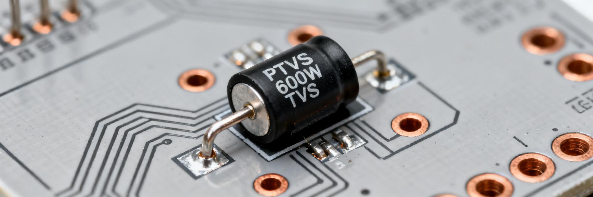
The PTVS6V0P1UP is a compact 600W transient suppressor chosen for board-level protection on low-voltage rails.
Datasheet-rated peak pulse power is 600W for the standardized 10/1000 µs waveform; typical pulse currents and clamping behavior place it among common SOD-128 solutions.
This article unpacks key specs, a practical test method, measured behavior, and US-focused design and sourcing guidance for engineers.
Point: Purpose is practical, data-driven evaluation.
Evidence: The write-up covers device class, critical electrical and thermal limits, waveforms/equipment, and measured Vclamp vs Ipp with survivability sequences.
Explanation: Readers will get actionable layout checklists, procurement acceptance steps, and reproducible test practices to validate protection on USB and other low-voltage rails.
Background & Intended Use
What the PTVS6V0P1UP is (device class & packaging)
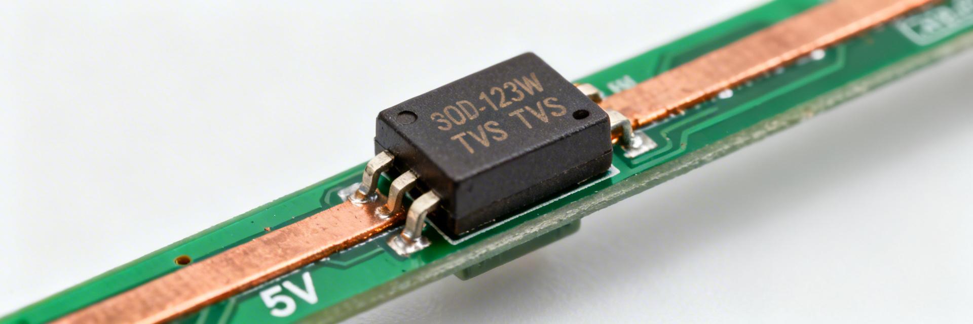
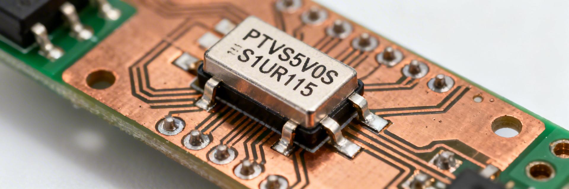
Point: The device is a uni-directional TVS diode in a small SOD-128 package for low-voltage rails.
Evidence: Typical breakdown in the 6–8 V region, reverse standoff suitable for 5 V systems, and a 600W PPPM rating for short high-energy transients.
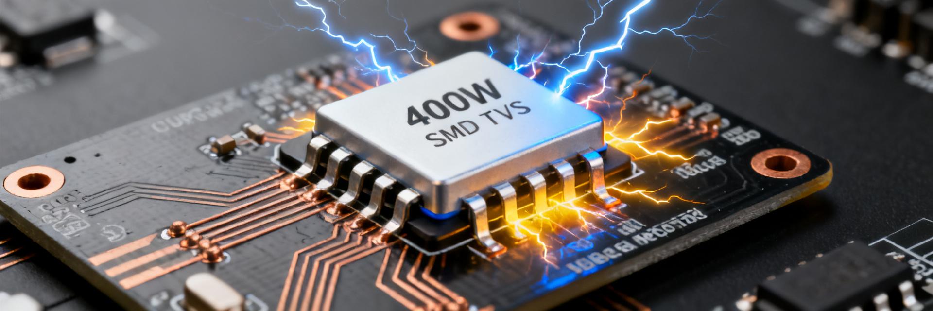
Explanation: The SOD-128 footprint minimizes board area while the 600W rating gives short-duration energy handling for inductive kickback and surge events.
Typical Application Scenarios
- ✔ USB and low-voltage power rails: Suppresses ESD and surge from cables entering the board.
- ✔ Board-level surge protection: Sacrificial clamp for inductive switching transients.
- ✔ Consumer interfaces (data lines): Protects downstream ICs from pulse overvoltage.
- ✔ Telecom and metered equipment: Limits damage during lightning-induced surges at input nodes.
Key Datasheet Specs
Point: Key electrical parameters determine suitability for a rail.
Evidence: The part lists PPPM = 600W (10/1000 µs), VRWM near 5.0–5.8 V, V(BR) typical ≈7 V, and clamping in the low double-digits at rated Ipp.
| Spec | Symbol | Test Condition | Typical / Value |
|---|---|---|---|
| Peak pulse power | PPPM | 10/1000 µs | 600 W |
| Reverse standoff | VRWM | DC | 5.0 V (typ) |
| Breakdown voltage | V(BR) | 1 mA | 6.5–7.5 V |
| Clamping voltage | VCL | Ipp (see datasheet) | ∼10–12 V |
| Peak pulse current | Ipp | 10/1000 µs | Calculated |
Thermal & Package Limits
Point: Thermal resistance and junction limits govern repeated-pulse survival.
Evidence: SOD-128 has relatively low thermal mass and higher θJA than power packages; max junction commonly 150°C.
Explanation: Use PCB copper pours, thermal vias under ground pads, and de-rate pulse repetition; plan for single 600W pulse survivability but limit repeated pulses without cooling.
Test Setup & Methodology
Point: Choose waveforms that match expected threats.
Evidence: 10/1000 µs is standard for surge capability; shorter 8/20 or ESD-style pulses highlight clamping dynamics.
Explanation: A high-current pulse generator, wideband current probe, and HV-capable oscilloscope are required; use low-inductance cabling and rated safety barriers during tests.
Test Fixtures, PCB Layout for Reliable Results
Point: Parasites distort clamping readings.
Evidence: Long traces add inductance, raising measured Vclamp and ringing.
Explanation: Mount DUT directly on a short, low-inductance fixture or a PCB with a solid ground plane, minimize lead lengths, and place measurement probes at standardized points to ensure reproducible V–I characterization.
Measured Performance & Test Data
Point: Report Vclamp vs Ipp and the breakdown knee.
Evidence: Typical devices show V(BR) ∼7V and clamping near 10–11V at rated surge current for a 600W part.
Explanation: Produce a V–I curve (Vclamp on Y, Ipp on X), capture oscilloscope traces for current and voltage, and record pre/post leakage to detect parametric shifts.
Thermal Performance & Survivability Tests
Point: Use a staged pulse sequence to characterize survival.
Evidence: Single 600W pulse followed by repeated pulses at 50–75% energy reveals thermal drift; acceptance often defined as <10% change in V(BR) and no visible damage.
Explanation: Log temperature, Vclamp, and leakage; if parameters shift beyond limits, increase package or add surge coordination elements.
Application Examples & Component Comparison
Point: Match VRWM to rail and clamp to IC tolerance.
Evidence: Choosing VRWM slightly above rail prevents operation in normal use; clamping must stay below damaged voltage of downstream parts.
Explanation: For ≤5V rails, pick parts with VRWM ≈5 V and low Vclamp; if higher energy surges expected, prioritize higher Ipp or larger package options.
How it Compares to Higher–Voltage or Different–Package Options
Point: Trade-offs are energy vs footprint.
Evidence: Larger packages handle more energy with lower thermal rise but use more board area and may clamp at higher voltages.
Explanation: Prefer the SOD-128 600W part where space is constrained and surge energies are moderate; shift to larger parts for repeated high-energy events.
Design & Sourcing Checklist
PCB & System-level Integration Checklist
- Place TVS adjacent to connector.
- Provide continuous ground plane.
- Use thermal vias for repeated surges.
- Coordinate series fuse upstream.
- Minimize loop area for return.
- Specify correct reflow profile.
- Include test pads for measurements.
- Document acceptable Vclamp limits.
- Consider surge coordination.
- Define post-surge pass criteria.
Procurement, Acceptance Testing & Documentation
Point: Verify parts with incoming lot tests.
Evidence: Request sample surge test data and perform lot acceptance using a defined 3–pulse protocol (single rated pulse + two reduced-energy repeats).
Explanation: Retain traceability, record pre/post electrical parameters, and require labels and lot IDs for each delivered reel/sample.
Summary
The PTVS6V0P1UP is a high-reliability 600W TVS diode in SOD-128. By validating clamping behavior through standardized testing and following rigorous PCB layout guidelines, engineers can ensure robust protection for 5V rails and sensitive downstream electronics.