PTVS7V5U1UPA Datasheet Analysis: Key Specs & Metrics
The introduction distills the numbers an engineer must see first when selecting a TVS for single-line protection: reverse standoff (VRWM), breakdown window, clamp voltage under rated pulse, and pulse-handling capability (IPP and transient power). This article extracts the decisive values from the component datasheet, explains how each spec maps to real circuits, and supplies practical validation checkpoints — from bench pulse tests to PCB layout rules — so designers can confirm the PTVS7V5U1UPA meets system-level resilience and safety targets.
Product Overview & Typical Use Cases (Background)

What the PTVS7V5U1UPA is
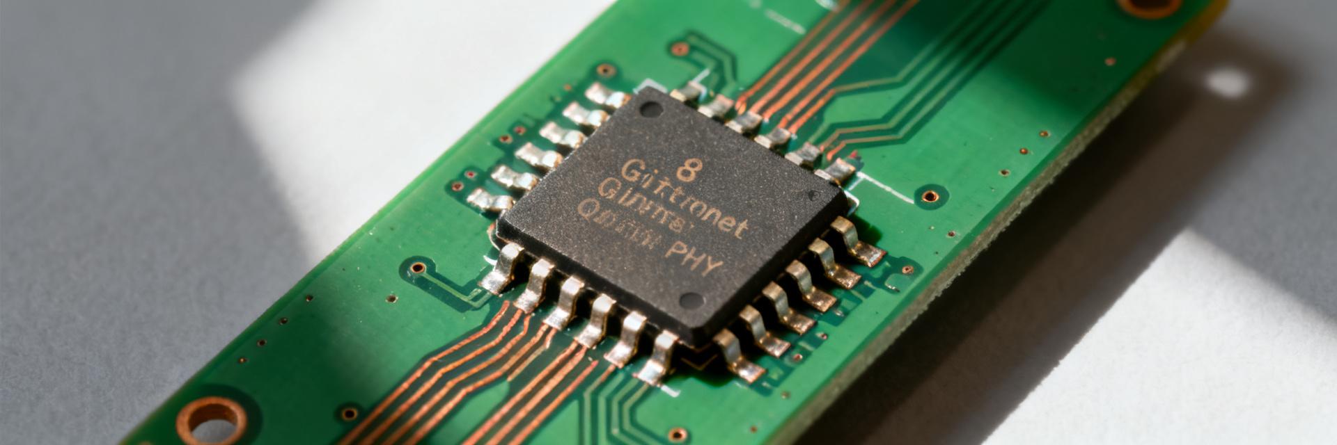
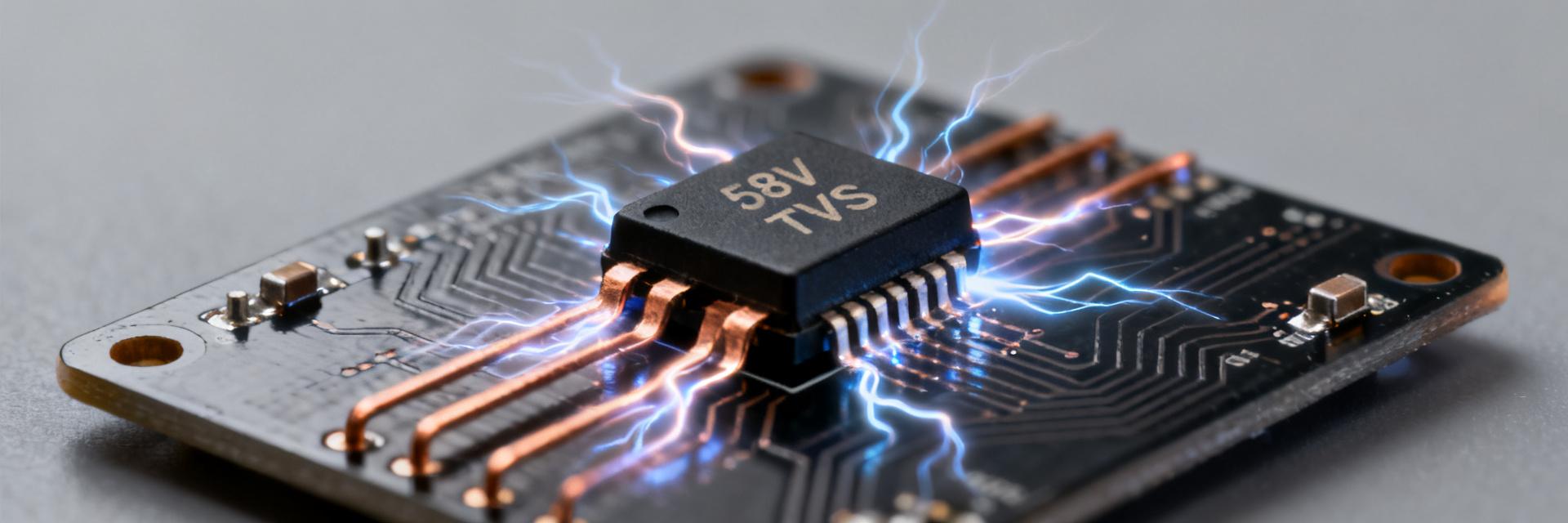
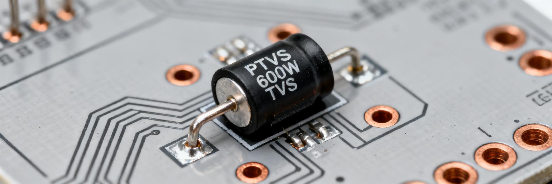
Point: The device is a unidirectional transient voltage suppressor in a compact SOD-style package intended for single-line power and I/O protection. Evidence: The part is characterized by a 7.5 V reverse standoff (VRWM), a defined breakdown window, and a transient power rating targeted to clamp short surge events. Explanation: That electrical identity makes it appropriate where low standoff and tight clamp behavior are required, for example protecting 5 V rails, input connectors, and sensitive regulator inputs while minimizing PCB area.
Typical application scenarios
Point: Use cases include power rail clamping, single-line I/O protection, and transient suppression at connector interfaces. Evidence: The part’s low standoff and pulse-handling trade-off favor small-package, moderate-energy suppression rather than high-energy arrester replacement. Explanation: Designers choose these parts where limited board space and defined clamp levels are more important than sustaining repeated large-energy lightning strikes; typical placements are at connector entry points, immediately upstream of fuses or input regulators.
Absolute Maximum Ratings & Thermal Limits (Data analysis)
Power and pulse ratings
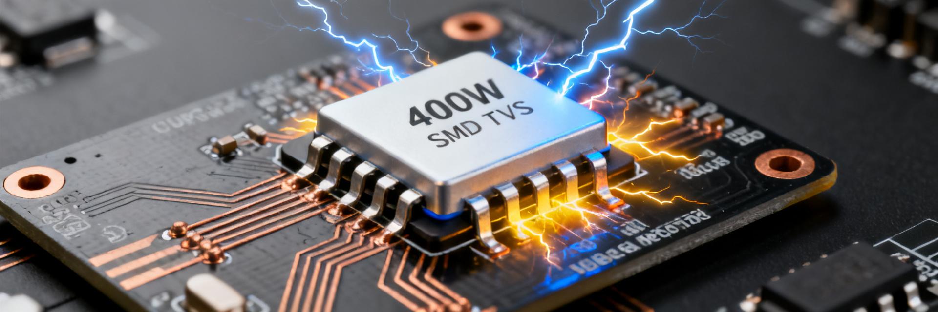
Point: The device specifies a transient power capability and peak pulse current for standardized waveforms. Evidence: A common transient figure is a 300 W rating (single-pulse condition) with IPP values provided for 8/20 µs and 10/1000 µs pulses. Explanation: Those specs tell engineers the energy the part can absorb in a single event and the expected peak current; datasheet pulse waveforms (8/20 µs for lightning-like pulses and 10/1000 µs for long switching surges) define test conditions used to derive IPP and Vclamp values, guiding selection against expected threats.
Temperature and derating guidance
Point: Thermal resistance and temperature limits govern continuous stress and repeated surge tolerance. Evidence: The device lists operating and storage temperature ranges plus junction-to-ambient thermal resistance (RθJA) values and often provides derating curves. Explanation: In practice, designers apply a simple derating rule: allow lower allowable surge energy for repeated events and ensure adequate copper and airflow to reduce RθJA; for repeated surges, increase safety margin or add series fuse to prevent thermal overstress.
Key Electrical Characteristics Explained (Data analysis)
Reverse standoff, breakdown and test conditions
Point: VRWM defines the nominal maximum working voltage before significant leakage; breakdown is given as a range measured at a specified test current. Evidence: VRWM = 7.5 V with a breakdown window quoted at a defined test current; leakage current is specified at VRWM. Explanation: In-circuit, the VRWM sets standby tolerance — the part must present low leakage at normal supply voltages — while breakdown and its test current determine when the device begins to conduct into avalanche.
Clamping voltage and dynamic behavior
Point: Clamp voltage at a specified IPP defines the worst-case voltage seen downstream during a surge; dynamic resistance describes slope of Vclamp vs. current. Evidence: Typical clamp values are cited for the standard pulse currents (e.g., a ~12–13 V clamp at a given 8/20 µs IPP). Explanation: Designers use Vclamp to verify that downstream components’ maximum voltage ratings are not exceeded; pick margin accordingly for faster pulses.
Surge Performance & Waveform Comparisons (Method/Guide)
8/20 µs vs 10/1000 µs
Point: Peak pulse current differs significantly between fast and slow waveforms. Evidence: Typical IPP values show much higher peak current for 8/20 µs versus lower IPP for 10/1000 µs. Explanation: Fast 8/20 µs pulses emulate lightning-induced transients; long 10/1000 µs pulses emulate slower switching. Choose based on the dominant threat.
PCB Layout & Placement
Point: Layout directly affects measured clamp performance. Evidence: Datasheet surge tests assume low-inductance connections. Explanation: Keep traces from protected pin to the TVS short, provide a low-inductance ground return, and place the TVS adjacent to the connector entry point.
Application Examples & Design Checklist (Case)
| Parameter | Typical Value |
|---|---|
| VRWM | 7.5 V |
| Vbr (test I) | Specified range at test current |
| Vclamp (IPP) | ~12–13 V at listed IPP (example 8/20 µs) |
| Transient Power | 300 W (single pulse condition) |
Example: Power/IO Protection
Evidence: The TVS clamps incoming transients before a fuse or upstream filter. Explanation: In practice, the TVS sits between connector and ground; during surge, the TVS clamps to the Vclamp level, the fuse removes sustained overcurrent, and the regulator sees a limited-voltage event.
BOM & Footprint Checklist
Evidence: Verify package outlines and land patterns. Explanation: Ensure pad geometry matches recommended footprint, reflow profile follows guidance, and consider adding a recommended fuse when system-level surge tolerance is limited.
Test, Validation & Troubleshooting Checklist (Action)
-
✓
Recommended lab tests & pass criteria: Essential tests include 8/20 µs and 10/1000 µs pulse injection at rated levels. Pass criteria: clamp within specified tolerance at IPP, leakage below specified µA at VRWM, and no structural degradation.
-
✓
Common failure modes & replacement criteria: Typical signs are increased leakage or visible damage. If failures stem from repeated energy exposure, upgrade to higher IPP or add series protection. Replace parts showing leakage increases.
Summary
Recap: Key numbers designers must lock down are VRWM = 7.5 V, the transient power rating (300 W single-pulse), and the IPP values tied to the 8/20 µs and 10/1000 µs waveforms that determine clamp behavior. Practical takeaways: verify layout (short trace, low-inductance ground), run bench pulse testing to datasheet conditions, and confirm standoff selection relative to system voltages. Review the PTVS7V5U1UPA datasheet for test-condition details, perform bench validation, and apply the checklist during design sign-off.