PTVS8V5S1UTR TVS diode: Specs Deep Dive & Pulse Data
Comprehensive technical analysis of low-voltage transient protection.
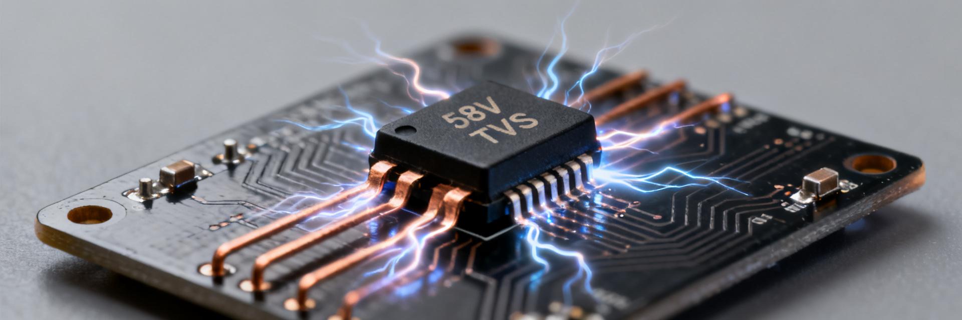
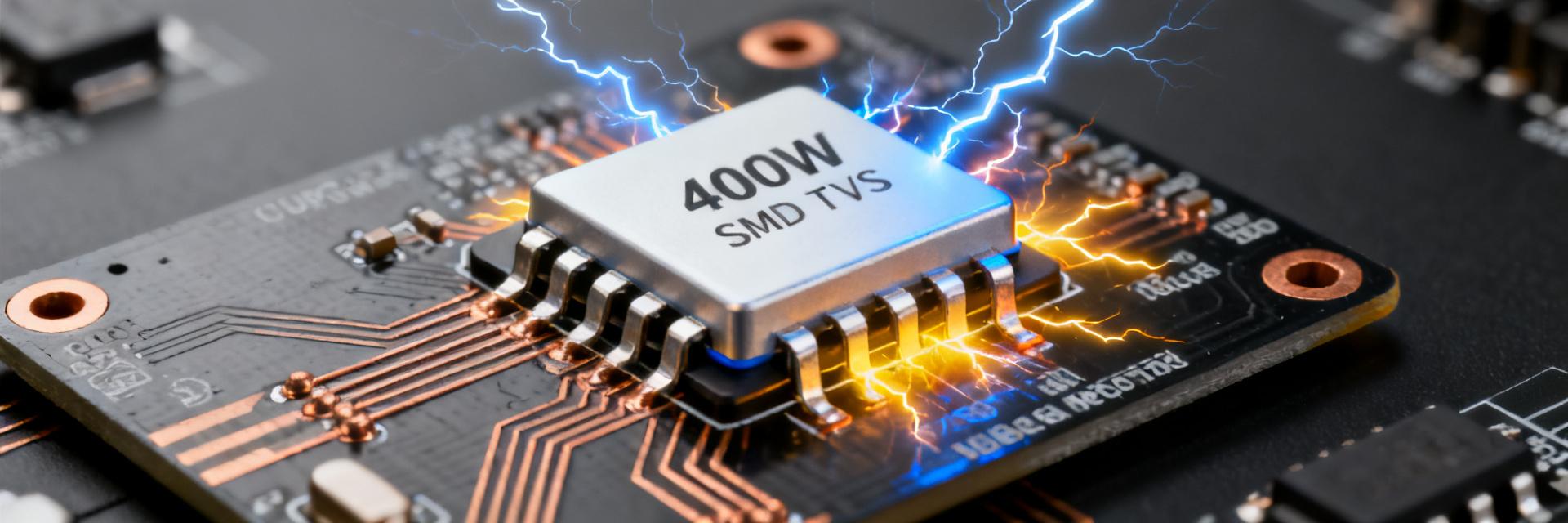
Point: The PTVS8V5S1UTR features a 400 W peak pulse power rating and a reverse standoff near 8.5 V; typical clamping under IEC-style pulses is ≈14.4 V.
Evidence: These numbers define system rail constraints and downstream component safety margins.
Point: This article uses waveform and datasheet data to explain real-circuit behavior under 8/20 µs pulses and guidance on board mounting.
Explanation: Stepwise test setup guidance and layout notes convert theoretical tables into actionable PCB choices.
Background — What This TVS Diode is and Where It’s Used

What a TVS diode does: Function and Operating Modes
Point: A TVS diode clamps transient overvoltage events by switching from a high-impedance reverse-biased state to a low-impedance conduction mode upon breakdown. Evidence: During normal operation, the device exhibits VRWM (reverse standoff) and microamp-level leakage; during a surge, it conducts and limits voltage to VCLAMP. Explanation: This unidirectional PTVS part is used on positive rails to protect against ESD, 8/20 µs surges, and lightning-induced transients.
Typical application spaces for an 8.5 V standoff part
Point: Common use cases include low-voltage power rails (5 V, 6 V), sensor interfaces, automotive logic lines, and industrial I/O. Evidence: An ~8.5 V VRWM provides headroom above nominal 5 V systems while ensuring the clamp remains below the input-tolerant limits of downstream ICs. Explanation: It is the optimal choice when the nominal rail plus transient margin falls between common VRWM options.
Key Electrical Specs — Quick Reference for Designers
Peak Pulse Power and Clamping Visualization
| Parameter | Example Value | Design Significance |
|---|---|---|
| VRWM | ≈8.5 V | Max continuous operating voltage |
| VBR | Consult Table | Breakdown threshold (VRWM < VBR) |
| VCLAMP | ≈14.4 V | Peak voltage seen by circuit during surge |
| IPP (8/20 µs) | See Datasheet | Max allowable peak pulse current |
Pulse Test Data & Waveform Interpretation
Interpreting 8/20 µs Pulses
The 8/20 µs waveform is a standardized surge shape with an 8 µs rise and 20 µs decay to half energy. Explanation: Clamped output yields an energy integral E = ∫v·i·dt. Designers must use the correct pulse width when converting Peak Pulse Power (PPP) to Joules for thermal sizing.
Lab Results vs. Datasheet
Bench VCLAMP may differ from datasheet values due to setup parasitics. Evidence: Probe inductance and ground loops introduce artificial peaks. Action: Minimize loop inductance and replicate datasheet source impedance to validate performance.
PCB and System-Design Considerations
Layout Best Practices
- • Place TVS close to the entry connector.
- • Minimize loop inductance to ground.
- • Use solid ground planes and short traces.
Thermal Management
- • Utilize thermal vias for heat spreading.
- • Consider series R to share energy.
- • Design for cumulative surge energy.